Honda Maintenance
Introduction
Engine Maintenance
Engine Oil Level
1. Lean the bike against a wall so that it is almost upright and in the straight ahead position.2. Remove the oil level gauge/dipstick and wipe it with a clean cloth.
3. Insert the gauge, but do not screw it in.
4. Remove the gauge/dipstick again and check to see if the oil is up to the upper marker.
5. Run the engine at idle for 2/3 minutes, switch off and recheck that the oil is to the upper mark on the dipstick.
Recommended oil is SAE 10W-40.
Engine Oil Change
Note that these engines do not have an oil filter as a replaceable item, there is a filter mesh inside the transmisission which is only accessable by removing the right hand crankcase cover, and the clutch unit also performs the function of a centrifugal type oil filter and can be cleaned out occasionally. The oil drains a bit quicker when the engine is warm, but be careful that the oil will be very hot. Not all the oil can be drained without stripping the engine, so a first refil of the engine after a rebuild will require more oil than a normal drain and refill.|
|
||
|
|
|
|
|
|
|
1. Remove the oil filler cap/dipstick.
2. Place a pan under the transmission and remove the drain plug (see
picture).
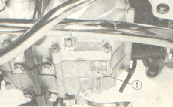
4. Refit the oil drain plug, making sure that the sealing washer is in good condition.
5. Refill the crankcase with the recommended oil, generally the amount required is marked on the crankcase near the filler.
6. Refit the oil filler cap/dipstick.
Screen & Centrifugal Oil Filter Cleaning
This is accesible by removing the right hand crankcase cover. To do this job you first need to drain the engine oil, unless you lay the bike down on its left hand side. Be aware that sometimes the crankcase gasket will be damaged, so do not do this job unless you either have a spare gasket or the time to go and get one if needed.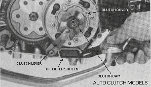
2. Remove the kickstart lever.
3. Remove the right hand crankcase cover.
4. Remove the oil filter screen, which is located at the bottom of the crankcase.
5. Clean the filter screen and replace.
6. For auto clutch models, remove the clutch lever.
7. Remove the clutch cam and then the clutch outer cover.
8. You should see that there is an accumulation of black dirt in 4 pockets around the periphery of the now exposed clutch centre, clean these out with a clean cloth.
9. Refit the clutch outer cover and then the clutch cam.
10. For auto clutch models, refit the clutch lever.
11. Check that the crankcase cover gasket is in good condition. If it is then refit the crankcase cover. If the gasket is damaged then replace this first.
12. Refit the kickstart lever, and anything else that you have removed.
13. If the oil was drained, then refill the engine with fresh oil. If not, then check that the oil level is correct (see sections above).
Air Cleaner
1. Remove the air cleaner cover.2. Remove the air cleaner element.
3. Clean the air cleaner element by taping it to dislodge dust, and then with a blast of clean air from the inside.
4. Refit the element and refit the cover.
Crankcase Breather
Some models have a plain pipe open to the atmosphere at one end, but if yours has the type where crankcase gases are recirculated back into the intake, then there will be a plugged pipe which will need the plug to be removed to drain off any water that might have collected in the system. Make sure that the plug is replaced afterwards.Tappets
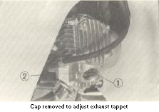
Both the OHV and OHC engines have rocker mechanisms in their heads, accessed by removing threaded aluminium caps, one for the exhaust valve (the lower/front one) and one for the inlet valve (the upper/back one). The tappets should be adjusted with the engine cold.Remove the caps to access the tappets, and the left hand engine flywheel
access panel.
Rotate the flywheel anticlockwise (counterclockwise) until the 'T'
mark on the generator is aligned with the index mark on the engine casing.
This is the Top Dead Centre (TDC) point, when the piston is at the top
of its stroke either at the end of compression or exhaust.
If the rocker arms won't 'rock' gently, then you are at the end of
the exhaust stroke and both valves will be open, so rotate the engine a
further 360 deg until the engine is at TDC at the end of the compression
stroke. Now both rockers should move slightly.
Insert a 0.002 in. (0.05 mm) feeler gauge between the tappet adjusting
screw and the top of the valve.
If it is too tight or too loose then adjust the gap by releasing the
tappet adjuster lock nut by about 1/4-1/2 of a turn, turning the adjuster,
retightening the lock nut and checking the gap again. You may need to do
it several times to get it right as the gap changes while you tighten the
locknut.
Repeat this for the other tappet.
Refit the tappet covers and the generator access panel.
Contact Breaker Points
There are 2 possible locations for the points, either as part of the flywheel generator or under a cap on the left hand side of the cylinder head.1. Flywheel Generator, Internal Location.
Usually the earlier models, plus the horizontal 50 & 70cc engines up until about 1980. Adjustment is done just by removing the small side cover, but replacement is a bit more tricky and if you have the correct puller it is much easier to remove the complete left hand engine side cover and pull the flywheel generator off.
The contact breaker points are a bit fiddly, but just as easy, and it
helps if you have a torch. Remove the round plate off the left hand engine
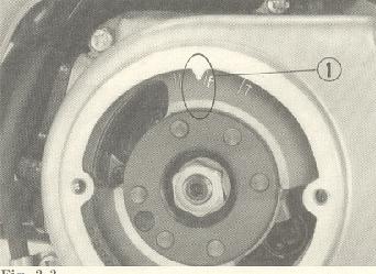
side cover. On the generator/flywheel you will see some marks and the letter
'F' and the letter 'T', and on the side cover at the top of the hole you
have uncovered is a triangular 'pointer'. Turn the generator/flywheel counterclockwise
and you should see the points opening as the 'F' mark passes the pointer.
Turn the engine relatively slowly and use the torch, if necessary, to watch
the contact breaker points. You may have to do this a couple of times to
get the hang of it.
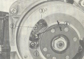 '2' is the
points screw, '4' is the gap you should measure.
2. Flywheel Generator, External Location.
Not so common, a typical example is the 1980-82 C50/70 models.
Remove the contact breaker cover (the plate on the left hand side of the engine).
Check the condition of the points. If the points faces are badly pitted then replace them, but if they are only greyish then you can gently file them flat.
Next set the points gap to between 0.012 - 0.016" (0.3 - 0.4 mm), using
a feeler gauge and rotating the engine to find the maximum points opening.
Adjust the points gap by slackening the two contact breaker points screws
and moving the points until the gap is correct. Retighten the screws and
recheck the gap again as sometimes the gap changes as you tighten the screws.
<photo c6>
Adjust by loosening the two contact point base plate screws and then
rotating the plate. Only slacken the screws just enough for you to be able
to move the plate. Rotating the plate clockwise will advance the ignition
time, and vice versa.
<photo c7>
3. Cylinder Head Location.
This type only requires the removal of the left hand cylinder outer side cover, usually held on with 2 screws, to remove the points. To set the points gap you need also to remove the left hand engine flywheel access panel.
The best way to check the timing is using a test lamp and the bikes battery. If you have nice long leads on your test light you can connect one end to the positive terminal of the battery. Disconnect the engine loom to main loom connector and connect the other lead to the Black/White wire on the engine loom. With the points closed the light will be on, whent the points open then the light will go off. As you turn the engine over, then the light should go off when the 'F' mark passes the pointer.
Spark Plug
Before removing a spark plug you should first remove the HT lead and then clean around the spark plug so that no dirt falls into the engine while the spark plug is being removed. If the spark plug is not going to be replaced within a short time, plug the spark plug hole with a plug of lint free cloth or paper to stop anything unwanted falling in.Try and avoid using any form of wire brush anywhere near a spark plug as small fragments end up getting caught up inside them and the insulator becomes scored. Both these things reduce spark plug life. If your spark plug has grown oily and gummy it is best to buy a new one (note that word "one". We are not talking here about needing 4, 5, 6, 8, 10, 12 spark plugs, now are we?). Alternatively, carefully scrape the worst off the metal parts with an old screwdriver.
Check that the HT cable is not cracked and that the spark plug cap is secure.
Cam Chain
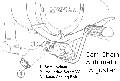
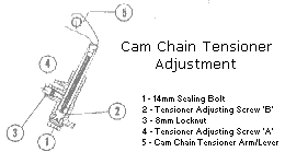
1. Start the engine and let it idle. If you have just rebuilt the engine then let it do so for at least 10 minutes to make sure the oil system is back to normal.2. Loosen the 8mm locknut, located just under the generator cover, and slacken the tensioner adjusting screw about 1/2 of a turn. The cam tensioner should now adjust itself and any cam chain noise die away.
Carburettors
There is a wide range of carburettors fitted to these bikes, both down draught and side draught. They all have some combination of screws to adjust and appear quite complicated when first approached. The most important thing to remember is that you are not going to be able to adjust anything with the engine cold except to put the screws to their suggested basic setting. To optimise the performance, or to solve a problem you are first going to have to make sure the engine is nicely warmed up and the choke is fully off. Be wary of assuming that a problem must be a carburettor one, other things can create the same kinds of faults as you would expect with a carburettor.The first thing to do is to make sure that the tappets, spark plug, points, clutch are all properly adjusted and functioning as they should. If the bike produces blue smoke from the exhaust then you are burning oil, if it is producing black smoke then it is burning excess fuel (maybe the carburettor is flooding?). Make sure that the oil level is correct, the brakes are well adjusted and the tyre pressures correct. It is worth putting the bike on its centre stand and making sure that the chain is well adjusted and without any tight spots. If the bike is fairly new to you, make sure that the cam timing is correct as someone may have reassembled the engine incorrectly. Check there are no cracks in the intake pipe, run the engine and either dribble some fuel around the intake pipe joints to see if the engine note changes (if it does then fuel is being sucked in somewhere which means there is an air leak on the intake pipe gaskets), or use about 12-18" of garden hose and with one end to your ear listen for any hisses around the joints. On some models the battery is part of the ignition system, make sure that the battery is well charged.
Make sure that the throttle cable moves freely, and if your bike has a choke cable then make sure that the choke is being opened and closed correctly and is not sticking part closed. There should be a few degrees of free play at the throttle twist grip, if not then the throttle valve will not be returned to its stop properly. Adjustment of the cable free play can be done at either end of the cable.
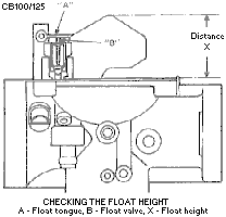
Check that the fuel lines are in good condition and are not blocked, including that the filter mesh inside the fuel tap/petcock is not blocked. If the bike has not been used for some time then the carburettor may need to be removed and stripped down, and the aluminium parts soaked in some form of cleaner to make sure that the fuel ways are not blocked. While the carburettor is apart, check that the float valve is still in good condition and that the float height adjustment is correct (see below). If you have fitted fuel filters, or are planning to do so, remember that your are dealing with a gravity fuel feed here, a whole lot different from a system with either a mechanical or electric pump. If you fit a filter down by the carburetor you might find fuel doesn't flow at all as the fuel exerts less force their and are more prone to air locking. Filters are best fitted just under the tank outlet and in such a way that no air pockets can form in them.
Basically, the carburettor is always the last thing you ever adjust.
There are 3 things you can adjust on a carburettor, other than the choke:
Air, Fuel, and the Throttle Stop. Adjust the air and the fuel and
speed will change etc. Adjusting carburettors is not difficult if the engine
is functioning fine, it is just a process you go through. The next thing
to realise is that the only way to affect the carbuaration for anything
beyond about 20% throttle open is by raising or lowering the needle in
the throttle slide. Those little screws on the side only adjust the idle
and very low throttle openings, and they are only fitted because it is
so difficult to manufacture a carburettor of this size with adequate pre-set
settings. If you are having problems with the engine at over 20% throttle
and the carb is not flooding/blocked then the problem is elsewhere. Even
a wrongly set throttle slide needle is unlikely to cause a noticeable problem
unless you live on a mountain top or in some humid jungle.
Main Jet/Slide Needle Adjustment
1. Warm up the engine and then ride it to a nearby slope, something steep enough to keep the max speed in 3rd gear to around 35-40 mph at wide open throttle (WOT). Ride up the hill and then, at the same moment, press the gear lever as if you were going for a "4th" gear (semi-auto gearbox)/pull in the clutch (manual gearbox) and switch the ignition off. Keep the gear lever pressed/clutch pulled so that it remains in neutral until you have cruised to a halt.
2. Remove the spark plug and check the insulator nose and electrodes for condition. What you want is a nice mid-brown colour on the insulator, if it is a dark brown and maybe a bit damp looking then you are running rich, and if the insulator is whitish and electrodes very greyish then you are running weak.
If you have a slide valve carburettor, then you can uscrew the large cap where the throttle cable enters the carb and pull out the grey-looking metal slide and its brass needle. This brass needle is generally held in place by a small snap ring and there is a often a choice of 3 grooves for this ring to fit. If you move the snap ring to a groove that makes the needle stick out of the slide more, then you will make the carb run weaker. If you move the snap ring to a grove that makes the needly stick out less then the carb will run richer. While you have the needle out make a note of the letter/number code on it and check that it is what is listed for that bike. Put it all back together and repeat the above test. If there is no change in the plug colour be a bit suspicious that there is another fault in the carburettor, like a blockage or that it is flooding.
Idle/Low Speed Adjustment.
Remove any bits of bodywork that will interfere with your work and then set the carburettor to its basic settings. Go and ride the bike around a bit to warm it up properly. Make sure that the choke butterfly is completely open otherwise every adjustment you make will be a waste of time. Generally you will only have 2 screws to adjust, the throttle stop and an air-bleed. Generally the basic setting for the air-bleed is 1-2 full turns out from fully screwed in.
1. Set the throttle stop screw to give you about 1300-1500 rpm, just
over the normal idle speed.
2. Turn the air-bleed 1/4 turn in and listen to engine speed. If it
improves then try another 1/4 turn, if not then try going 1/4 back out.
3. Keep repeating until you find the point where you think the bike
is running its best. If you can find no improvement, then leave the screws
set to the basic setting. If the bike is still not happy then there is
a problem somewhere.
4. Adjust the air-bleed 1/8 of a turn either way and look for the best
position. If the final air-bleed screw position is less than 1/2 turn out
from full in, or more than 2 1/2 turns out, then there is a problem with
the carb or the engine.
5. Readjust the throttle stop screw back to the idle speed.
6. Test the bike to make sure that there is not a flat spot in the
performance as you open the throttle.
Do not worry too much if you find that the engine seems quite insensitive
to the air-bleed adjustment, the vibration levels and quite rapid air flow
reversals at low engine speeds tends to bleed fuel out of the main jet,
particularly as the arburettor ages. ou will notice that almost all carbs
in the world these days are either down draught or side draught, and side
draught ones always incline down towards the engine at about 10 deg. This
allows fuel leaking from the main jet at idle to drain down into the engine.
If you find something like an ancient lawnmower with an up draught carburettor
then you will see it drips fuel out of the carb at idle.
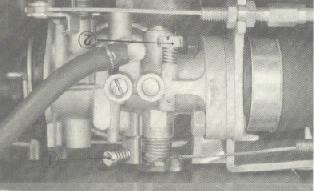 CF70 Side
Draught Carb.
Semi-auto Transmissions (Gearbox & Clutch)
Adjustment of the clutch should be done with the engine stopped. The adjustment screw is located in the centre of the pot shaped extension to the right hand transmission side cover.1. Slacken the locknut.
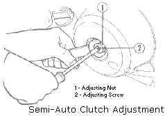
3. Turn the adjusting screw anti-clockwise until a resistance is felt.
4. Turn back clockwise for 1/8th of a turn and tighten the locknut.
5. Ride the bike and make sure it changes gear cleanly and that the clutch does not slip when going up hill.
Manual Transmissions (Gearbox & Clutch)
Brakes
Later models with drum brakes have a little pointer on the lever on the side of the brake itself to indicate if the brake shoes need replacing. For earlier bikes then you will have to remove the wheel and inspect the brake shoes themselves.Disc brake pads can be inspected and they usually have some kind of painted mark on the side of the pads to indicate if they need replacing.
Front Brake Lever
1. Check to see that the free play at the end of the front brake lever is about 1 in. (20 - 30 mm).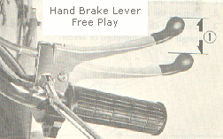
3. Check that the front wheel turns freely thhrough its full 360 deg, with the brake off.
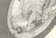
4. If the free play of the lever is incorrect then adjust the nut on the end of the cable at the wheel end. This is a special nut that turns in 1/2 turn steps. Rotating it clockwise ('A' on the picture) reduces the play at the hand lever end, and rotating it counterclockwise ('B' in the picture) increases the play. Check that the wheel is still free with the brake off when you have finished.
Rear Brake Lever
1. Check to see that the free play at the end of the froot brake lever is about 1 in. (20 - 30 mm).
3. Check that the rear wheel turns freely through its full 360 deg, with the brake off.
4. If the free play of the lever is incorrect then adjust the nut on the end of the cable at the wheel end. This is a special nut that turns in 1/2 turn steps. Rotating it clockwise ('A' on the picture) reduces the play at the hand lever end, and rotating it counterclockwise ('B' in the picture) increases the play. Check that the wheel is still free with the brake off when you have finished.

Drive Chain
For bikes with fully enclosed chains then there will be a plastic or rubber plug to remove to see the chain, or you can remove one half of the cover. The latter is recomended as it is always good to check the state of the sprockets as well, if the teeth are beginning to look 'hooked' then it is high time to replace them. If the chain has a split link to aid chain removal, then the rounded end of the split link retainer should be in the 'forward' position.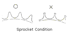
<insert split link picture>
2. Push up on the chain with one finger at the midway point between the sprockets and measure the slack. Repeat this at 6 in (150 mm) intervals around the length of the chain by rotating the rear wheel. It is necessary to check the whole chain as there may be tight and loose parts of the chain. If there are significant differences then the chain needs replacing. The chain slack should be between 15 and 25 mm (5/8" - 1").
3. To adjust the chain you need to slacken the rear wheel spindle: Remove the cotter pin/split pin from the spindle nut and slacken the nut by about 1 turn.
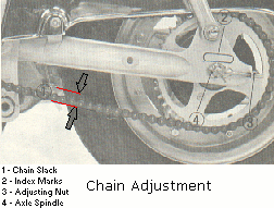
5. Turning the adjuster nut clockwise will tighten the chain, and counterclockwise will slacken it.. make sure you make the same adjustment each side otherwise the rear wheel will become misaligned. There are guide marks on either side of the swinging arm next to the spindle adjusters.
6. When the adjustment is correct, tighten the spindle nut and then the adjuster lock nuts. Check the tension once more in case it changed during the nut tightening operation.
Wheel Alignment
For this operation you need the bike upright and the front wheel in the straight ahead direction.1. Take a long piece of string and pass it round the bike once so that
it touches the tyres about 6-9 in (150- 250 mm) from the ground, and does
not touch anything else.
2. If the front and rear tyres are the same size then the string should
touch each wheel twice on each side. If the rear tyre is larger than the
front then it should touch the front tyre at the front and the distance
between the string and the back of the front wheel should be the same on
each side.
3. If the rear wheel does not appear to be aligned then you can correct
this by adjusting the chain adjusters. If the front and rear wheel appear
to be in the same line, but offset then it could be that one wheel has
the wrong spacers fitted. Anything else and it is likely that the forks,
the swinging arm, or even the frame, is bent.

Front Suspension
These fall into 2 main classes, leading link and telescopic forks.1. Leading Link
Rear Suspension
Bounce the rear of the bike to see how many times the bike bounces after you let go and to see if it makes any squeaks. If you push hard down on the back of the bike and then let go, the bike should freely spring back up and then do no more than a small dropping back. If the movement is not free then either the dampers or the swinging arm has seized, while if the movement of the bike is too much then the dampers need to either be refilled or replaced. Note that many of the smallest bikes and also many of the twin shock XL's seem to have quick wear dampers.Check that there are no oil leaks from the damper(s).
Put the bike onto its centerstand so that the rear wheel is free of the ground. If the bike does not have such a stand, then something like a beer crate should be used instead to support the bike.
Check that all the suspension nuts and bolts are tight and the rubber components are in good condition. Grab hold of the frame of the bike in one hand and the wheel in the other and try and feel if there is any movement in the swinging arm bushes. If there are then the bushes need to be replaced.
Wheels & Tyres
Electrical (non-ignition) Components
Battery
Check that the level is between the indicator marks on the side of the battery. If the fluid level is low, then top up with distilled water. If the battery fluid level continually drops, then suspect that something may be going wrong with the charging or the rectifier.If the battery needs frequent recharging then check to see if there is a layer of sediment forming at the bottom of the battery. If there is then the battery is at the end of its useful life as the sediment is the battery plates disintegrating.
Always remove the plugs from the battery cells before charging and check that the fluid level is incorrect. Never charge the battery in an enclosed space, nor with it still connected to the bike. Batteries contain acid, and give off flammable gases during charging. It is not unknown for batteries to explode during charging.
Brake Light Switches
Only adjust the brake light switches after the brakes have been adjusted. The front brake switch is not usually adjustable.The rear brake light switch will be down on the right hand side of the bike, suspended above the foot brake lever. Check that the light comes on at about the moment the brake lever free play is all taken up. Do not twist the switch during adjustement, only the nuts. As the switch ages it can sometimes become a bit fragile, so take care.
Headlamp Alignment
There are 2 screws to adjust the headlamp beam alignment, if you face the headlamp the up and down adjuster screw is on the top left side of the headlamp, and the left/right adjuster on the bottom right side.Adjustment of the headlamp should be done with the bike upright and
a rider sitting on it.
<photo c11>
General Lubrication
Most lubrication should be done during the major servicing, particularly as much of it requires stripping the bike down. Lubrication is essential to the long life of the bike, and stripping a bike has both benefits that you become more familiar with working on your machine plus you can discover problems before they become significant.Cables
Disconnect the brake, clutch and choke cables at there upper ends and lubricate the cables with a cable lubricant. Grease the lever pivot points. Do not lubricate the speedometer or tachometer cables as the lubricant can work its way into these instruments and affect the accuracy.
Suspension Pivots
These should be taken apart, the old grease cleaned off and fresh grease applied.
Brake Pivots
These should be taken apart and an approved brake grease used. Normal grease may liquefy at high brake temperatures and seriously impair the functioning of the brakes.
Drive Chain
This should have a 'top-up' lubrication every week if you are using the machine regularly. Occasioanlly the chain should be removed and thouroughly cleaned, as well as the sprockets, and fresh chain grease applied.
Centrestand Pivot
This is a fairly essential part that is often forgotten. On many models (CB/CG etc) people have a lot of trouble when the pivot pin seizes in the centrestand or even wears out the frame. The pin should be removed at least once a year and the pin properly cleaned and greased.
Other
Sidestand RubberSome sidestands have a little rubber piece on the foot. This wears, but if you replace it be aware that Honda sells them in different grades of rubber and your parts salesman can easily have put the wrong grade in the parts bin. The rubber is marked for the weight of bike it is suitable for.
Note: Some of the pictures on this site are from the official Honda CF50/70 workshop manual.